 Русский
 Français
 Chinese
OLTC devices diagnostic: many questions – one solution!
| NON-DEMOUNTABLE DIAGNOSTIC (DRM) → |
DEMOUNTABLE DIAGNOSTIC → |
CIRCULAR DIAGRAM → |
OSCILLOGRAPHY → | RESISTANCE MEASUREMENT → |
Nowadays, on-load tap changers (OLTC) are frequently found and used in the operation of modern power transformers. This is not accidental, because this type of switching device is convenient to operate due to the ability to regulate the voltage of the consumer without disconnection. However, does everyone use this functionality in practice? This is already a topic for a separate material.
An OLTC device in a power transformer is the largest and most sophisticated object with movable and rotating mechanisms and parts through which the nominal current constantly flows. Thus, having such a position, this device requires special attention and control in particular.
Basically, OLTC devices are divided into reactor and resistor ones, and while switching, an arc extinction occurs either in oil or in vacuum.
The principle of operation of an OLTC device, as well as any sophisticated object, determines its typical malfunctions, which require early determination and elimination. The process of operation of the device consists in one feature - a nominal current and short-circuit current (short circuit) flows through components of the device - a contactor and a selector, and when switching the OLTC, an arc extinction occurs at arc-extinguishing contacts of a contactor. These facts lead to carbon deposits and local heats. Here we would like to note that the prohibition on the switching in automatic mode will give a chance to reduce operational malfunctions by saving arc-extinguishing contacts of a contactor but all other nodes will still be exposed to electric current.
When understanding the principle of the OLTC operation and determining its inevitable operational "damages", it is possible to more specifically emphasize a number of major malfunctions that may occur:
- breakage of current limiting resistances;
- delaying and time difference of switching;
- desynchronization of shafts;
- backlashes in the drive mechanisms;
- bounce when switching;
- contactor or selector contacts burn;
- deformation/damage of an OLTC tank;
- etc.
Even if we know a number of possible malfunctions that can and should be determined using periodic OLTC diagnostic, there is another problem and it consists in that no one is engaged in such diagnostic. It means that many defects that could be detected at an early stage remain unnoticed until they develop into critical ones.
Undoubtedly, it is possible to measure the resistance at each tap, that will indicate a discrepancy with the nominal data, or take the oil for analysis, but it will require labor effort to collect anamnesis and wait for results in spite of the accuracy of such diagnostic. Therefore, another approach is needed in order to localize the problem, particularly, OLTC diagnostic conducted with specialized modern devices that:
- automate the diagnostic process;
- do not require much labor effort and time to work;
- save the company money;
- extend the service life of the device;
- as for planned diagnostic, exclude the need to demount OLTC;
- define problems at an early stage.
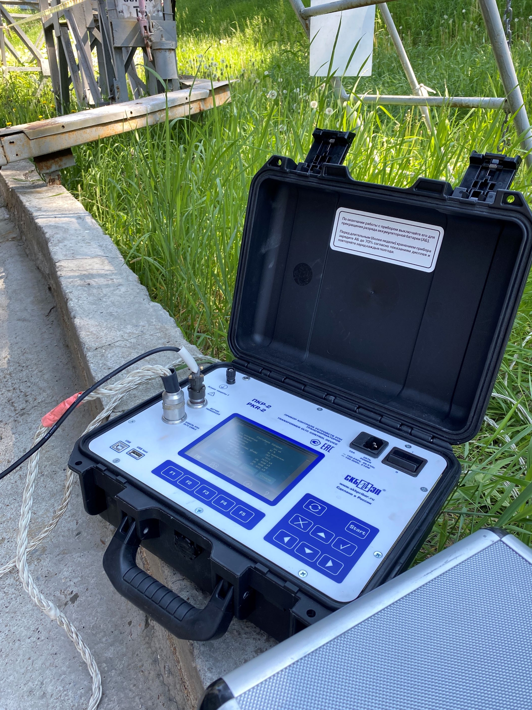
In accordance with the above mentioned requirements, the Russian manufacturer of diagnostic equipment, SKB EP LLC, produces and sells two instruments PKR-2 and PKR-2M. They realize a fundamental function to register an oscillogram of the contactor and a circular diagram simultaneously in all phases, that allows you to analyze the mechanical component of an OLTC.
Moreover, the instruments have a "check" mode, which gives an opportunity to conduct a settling-up of an OLTC after repair or before its commissioning.
NON-DEMOUNTABLE OLTC DIAGNOSTIC (DRM METHOD)
An interesting and popular function of the instruments can be the DRM mode, which finds its application on resistor OLTC. It is designed for rapid diagnostic or initial check, because it allows you to check the status of the contactor without opening the tank of an OLTC, that gives clear advantages (this mode is implemented in PKR-2M modification by default).
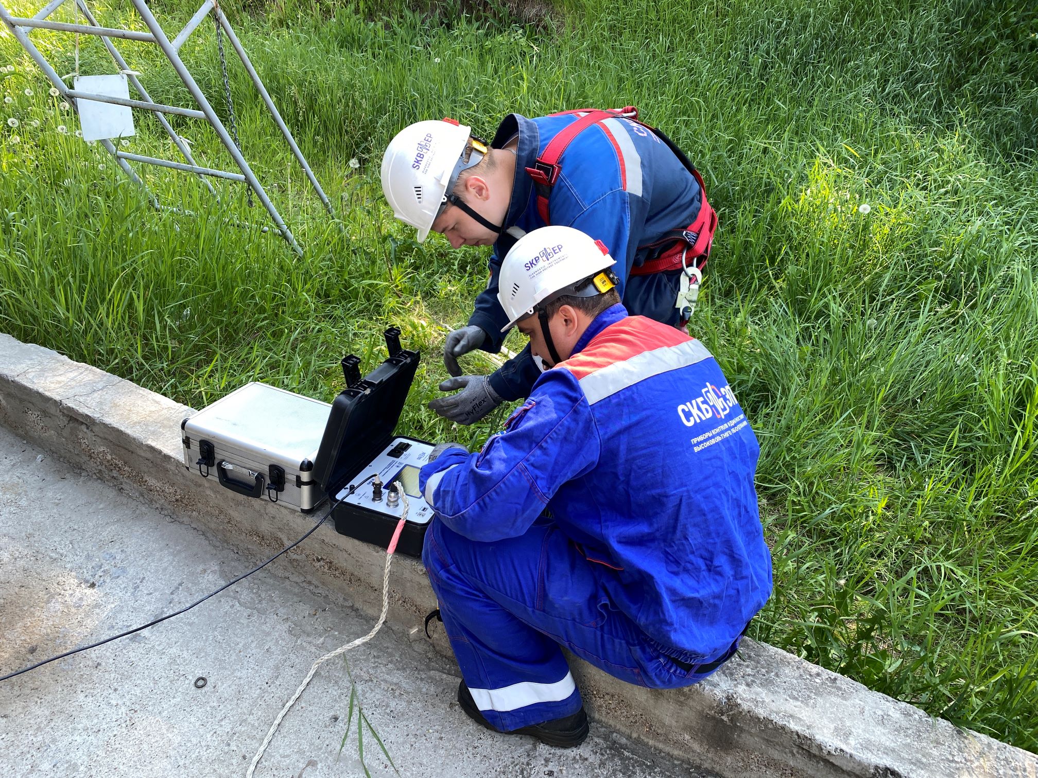
This diagnostic method is quite simple to carry out because it is just necessary to connect to bushings of a power transformer where an OLTC is installed, start the measuring process on the instrument and switch an OLTC. The result of such diagnostic will be an oscillogram implemented in PKR instruments and it will match the form of the usual "demountable graph" thanks to a special mathematical modification (Fig. 1).
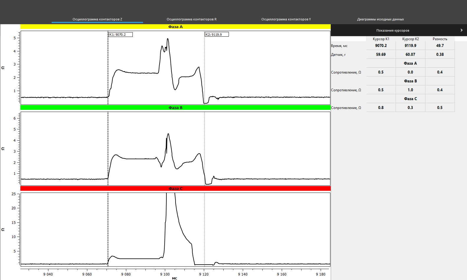
After receiving a complete oscillogram registered in DRM mode, the user has the opportunity to view each peak at all stages of an OLTC by scaling, both on the screen of the instrument of PKR group and on the computer/laptop screen (hereinafter - PC) in a special software. Even such an express analysis will already allow us to determine possible incipient defects and malfunctions of the contactor (Fig. 2 and Fig. 3).

DRM method diagnostic is suitable for assessing the condition of a contactor and checking the sequence of its operation. Based on the results, it is possible to evaluate the integrity of the resistances, the synchronicity of operation and the operating time of a contactor.
On the other side, a demountable method of diagnostic allows you to check both the contactor and the selector of an OLTC, particularly the order of operation of its elements. This type of diagnostic is more common, it is used to localize the damage site, when setting up an OLTC before commissioning or for adjustment after repair work completion.
DEMOUNTABLE DIAGNOSTIC OF OLTC
This diagnostic method is the most understandable and obvious. Its application extends to both resistor and reactor OLTCs, however, with a difference in types of recorded data, according to design features and requirements:
- a circular diagram and an oscillogram of the contactor operation are recorded in resistor OLTCs;
- only a circular diagram is recorded in reactor OLTCs, as here there is no possibility to take an oscillogram due to the technical features of this type of device.
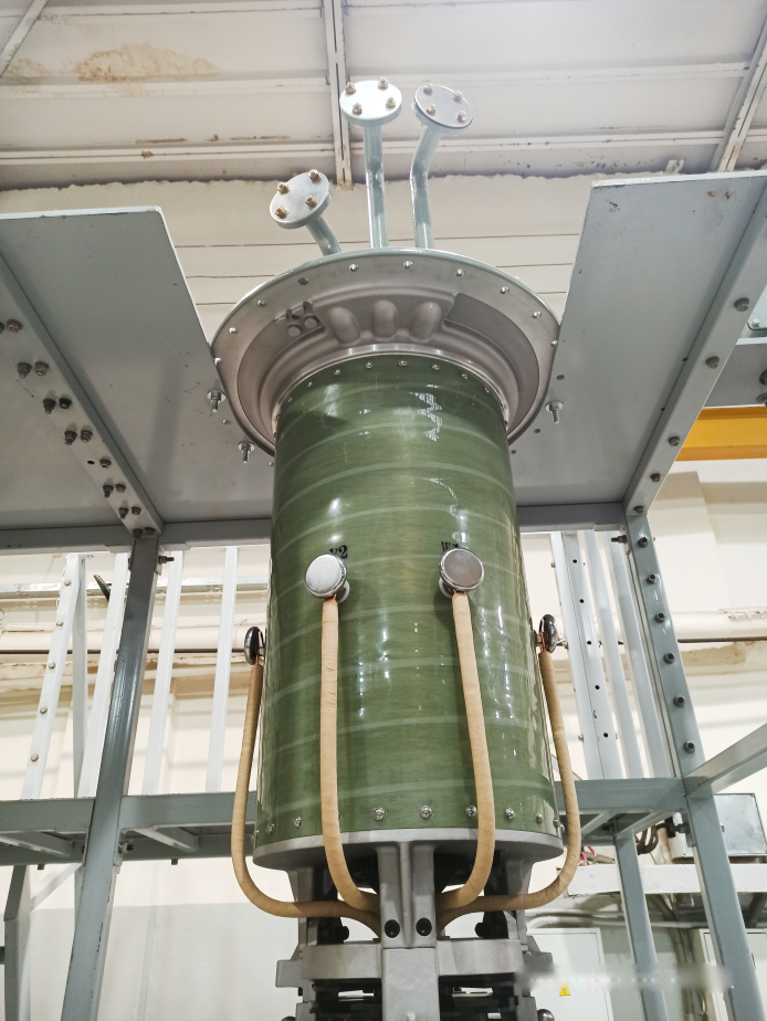
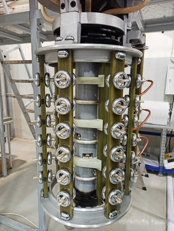
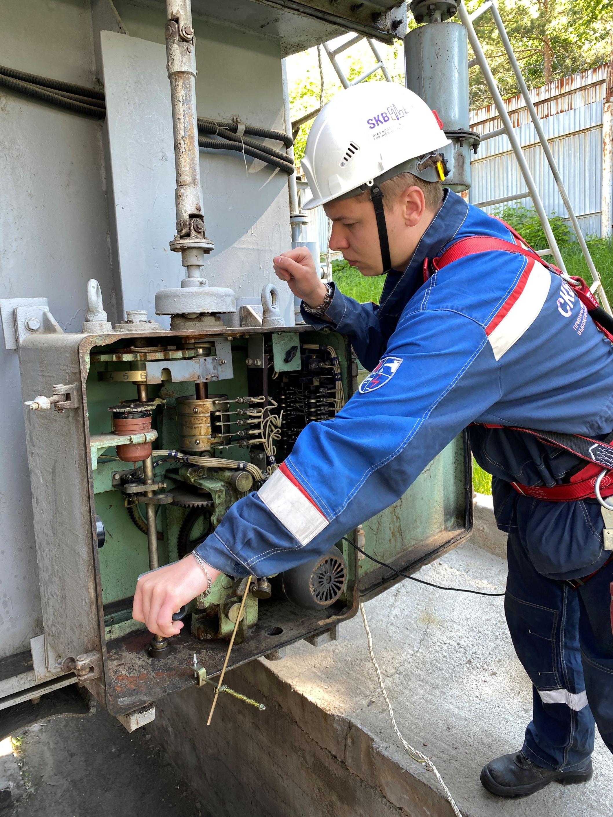
Such diagnostic method is more labor-intensive and long, starting with the preparation for the diagnostic and the process itself and finishing with the return assembly of an OLTC for the workflow. It is necessary to open a tank cover of an OLTC and connect inside the tank of the power transformer, consequently, it is needed to partially or completely drain the oil to connect the instrument of PKR group to the fixed contacts of the contactor. (Fig. 4).
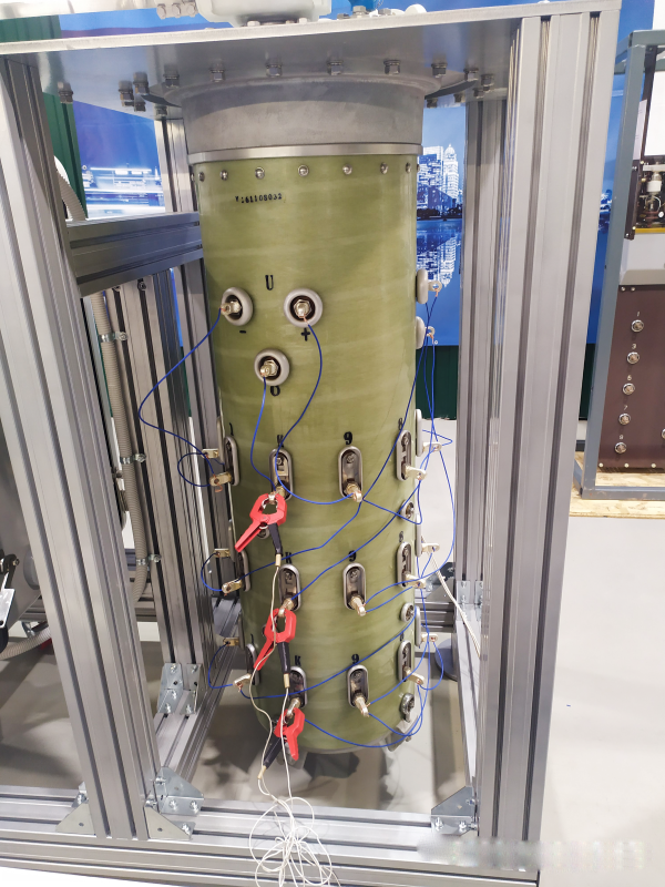
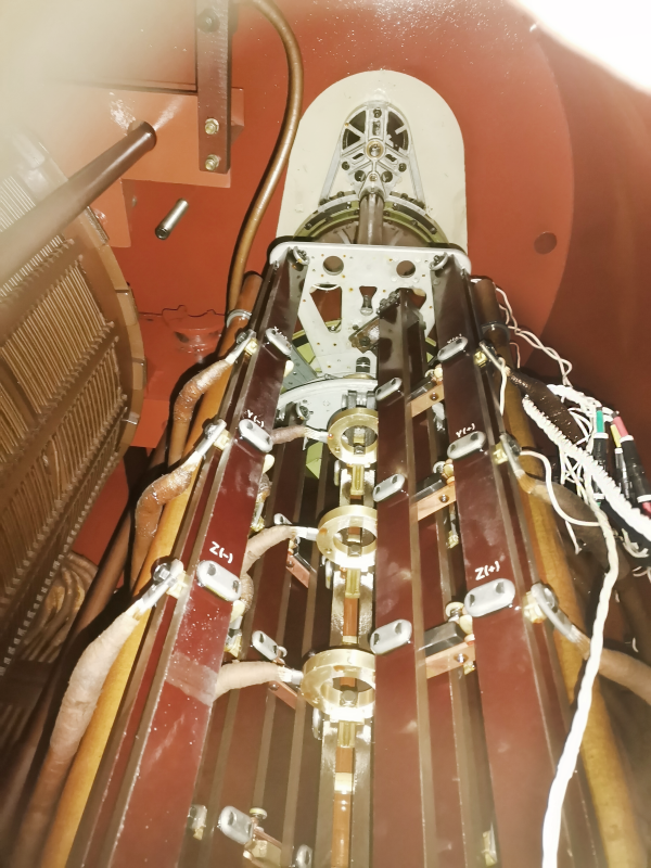
Figure.4. Direct connection of the test cables of PKR- and PKR-2M instruments to the contactor contacts
When developing PKR-2 and PKR-2M instruments, special difficulties that occur during demountable diagnostic were taken into account, so special contact probes were implemented (Fig. 5) so that it was possible not to drain the oil, or to make it partially drained. Then, in cases when a tank is without oil, but it is not removed, and contacts are in depth, the use of probes excludes the "diving" of a diagnostic specialist into the tank itself, that may not be safe.
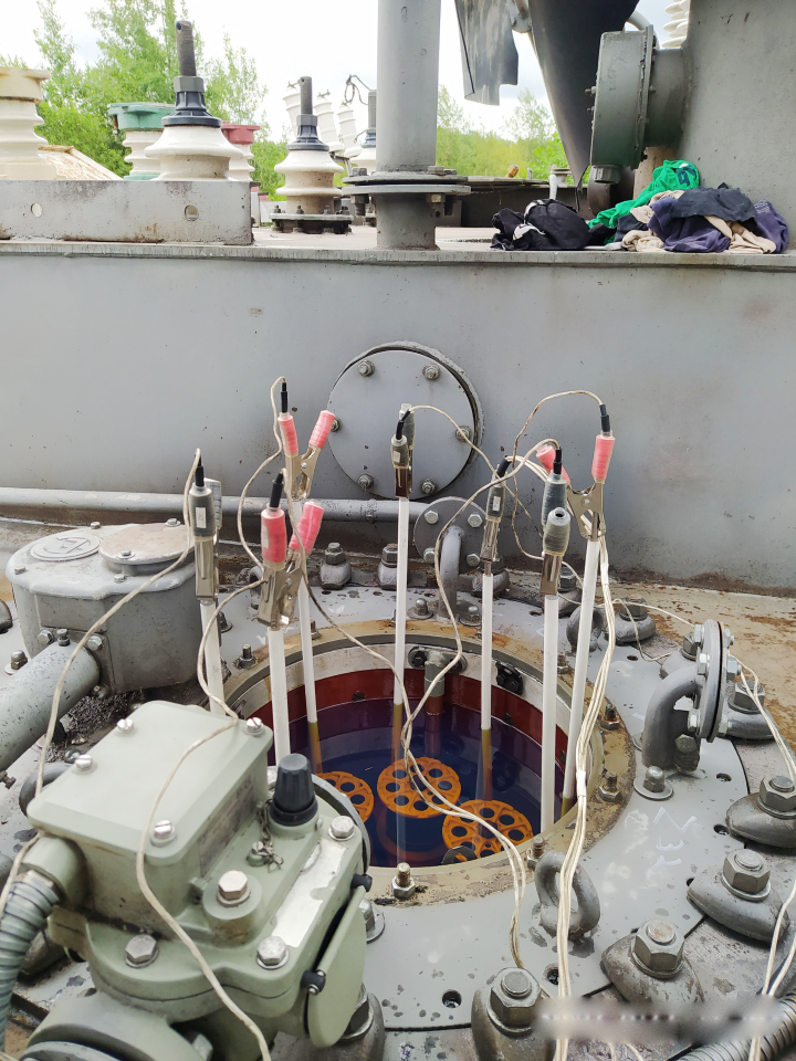
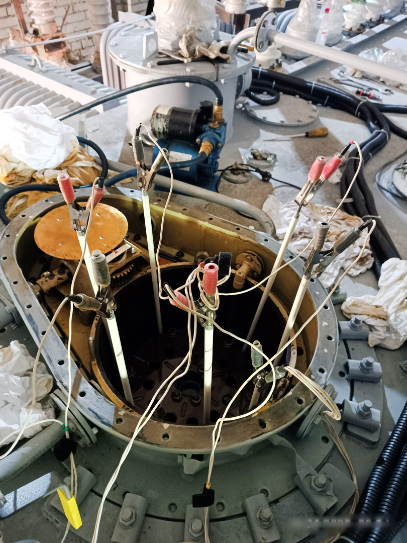
Figure 5. Working with the contact probes from the additional equipment of the instruments from PKR-2 and PKR-2M groups
DEMOUNTABLE DIAGNOSTIC OF OLTC DEVICES: CIRCULAR DIAGRAM
To register a circular diagram, the instruments of PKR group are equipped with a special angular movement transducer DP22 (Fig. 6), which is installed on the drive shaft of the device with a help of special axes and bushings which consider different designs. The transducer allows you to measure the angle of rotation and the number of revolutions of the shaft of an OLTC device in the measurement range 0 - 360º.
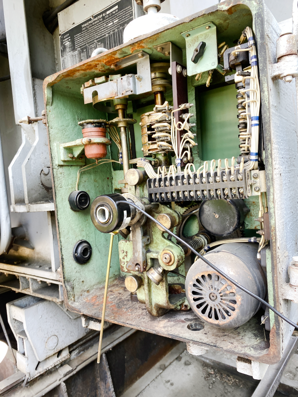
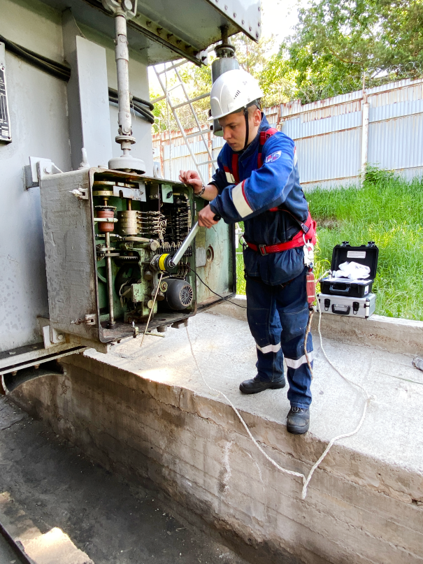
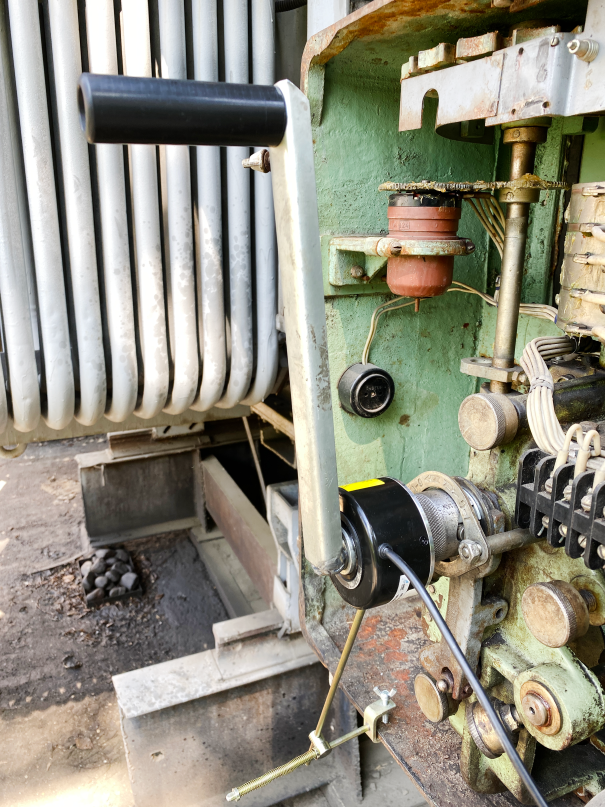
Figure 6. Working with DP22 transducer for taking circular diagrams of OLTC devices in transformers
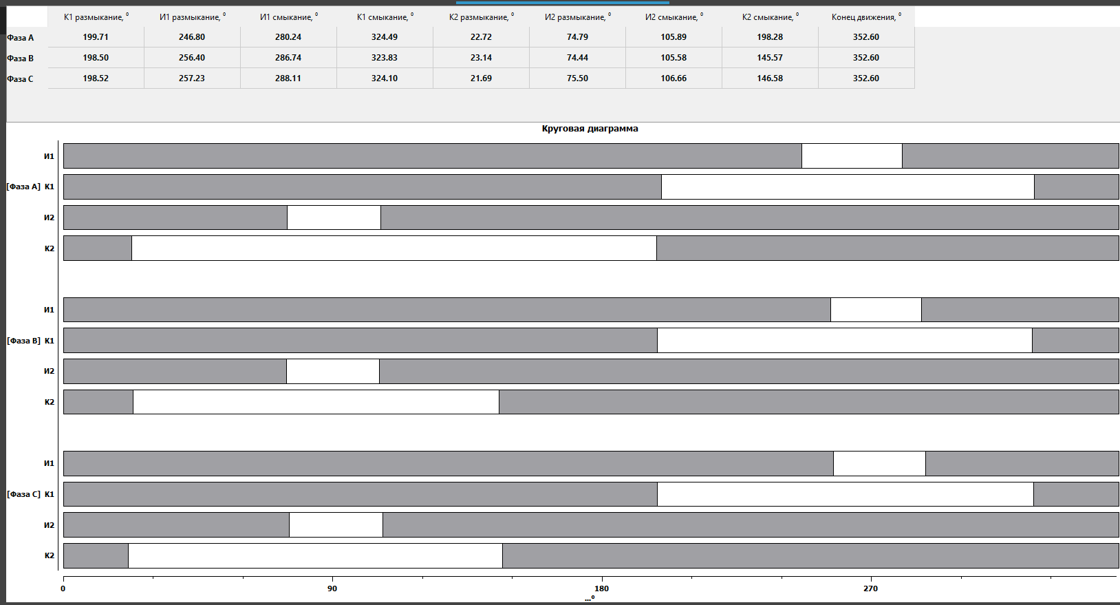
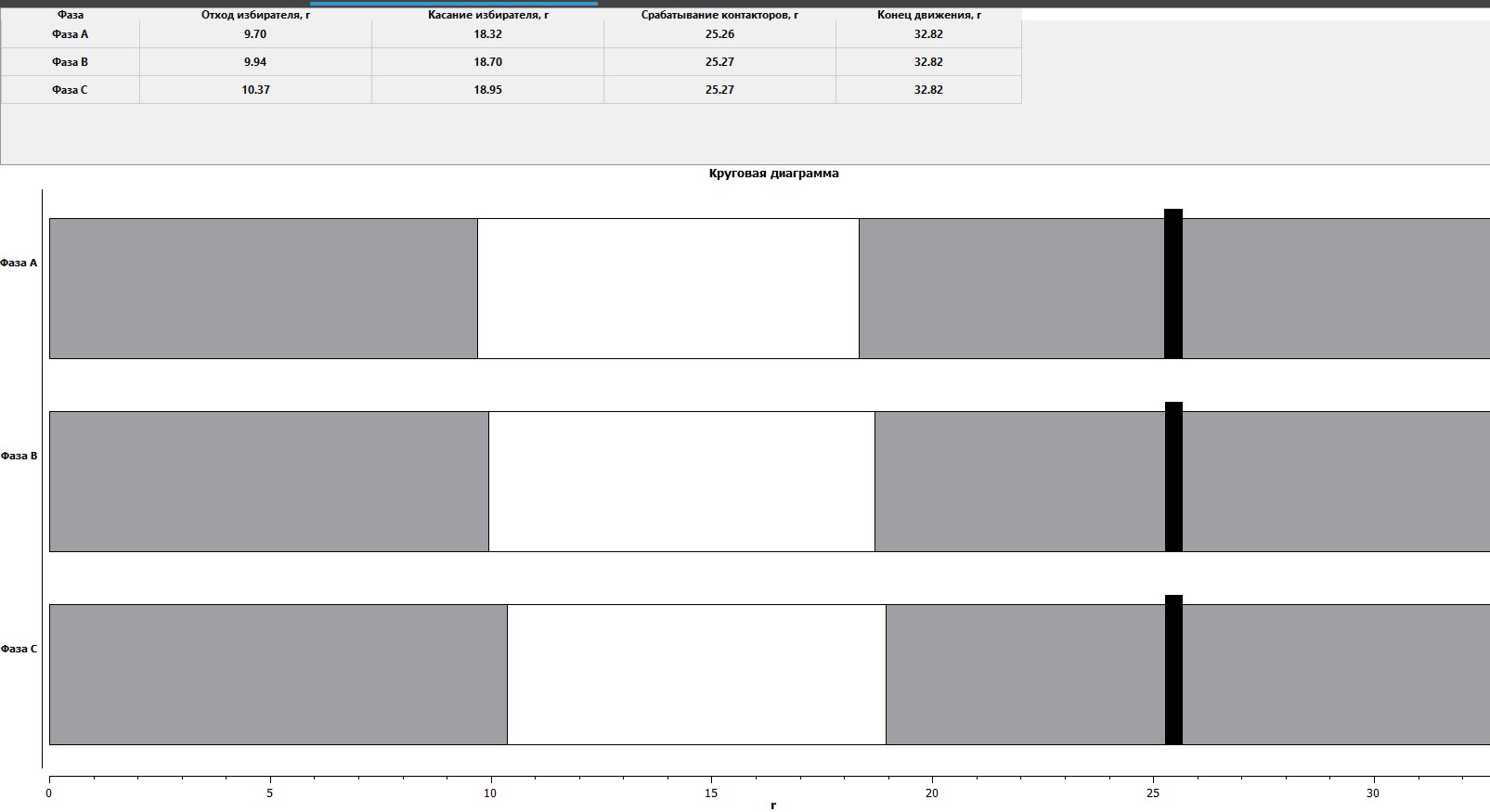
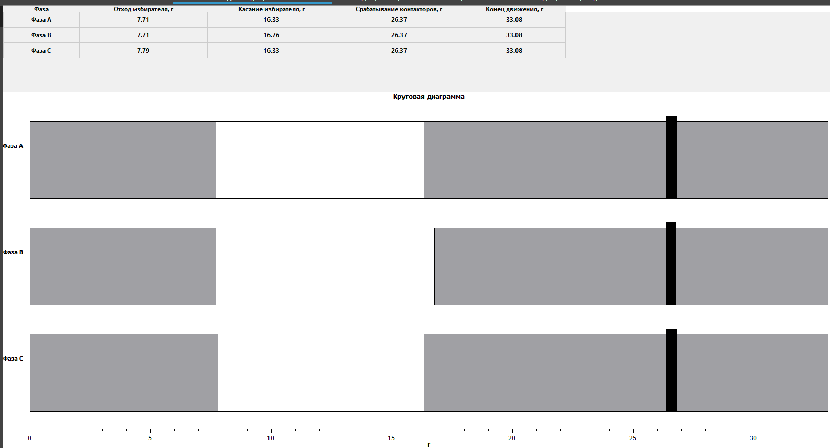
Diagnostic using circular diagrams allows you to see the entire process of switching an OLTC and assess its condition by determining the operation backlashes. According to the results, the operation of the main nodes and their sequence of actions, angular values for all phases and possible defects that can be seen with the unaided eye are clearly shown on the display of the PKR group device or in the software on the PC. Switching over all three phases should be synchronized, so that the slightest shifts and differences are immediately visible (Fig. 7).
For instance, on the circular diagram of resistor OLTC, the difference in the rotation of the selector and the contactor operation in the forward and reverse direction is clearly visible, as well as the selector work synchronicity (Fig. 8 and Fig. 9).
The representation of circular diagram for reactor and resistor OLTC will be different, due to technical differences.
DEMOUNTABLE DIAGNOSTIC OF RESISTOR OLTC: OSCILLOGRAPHY
In addition to the circular diagram, the contactor oscillogram is recorded in resistor OLTCs, because it is important to control the stages of its switching.
When analyzing resistor OLTCs, the PKR group instruments are connected to the fixed contacts of the contactor and in order to obtain the most reliable data, the contactor should switch in oil, therefore the use of contact probes in this case is an essential condition (Fig.5).
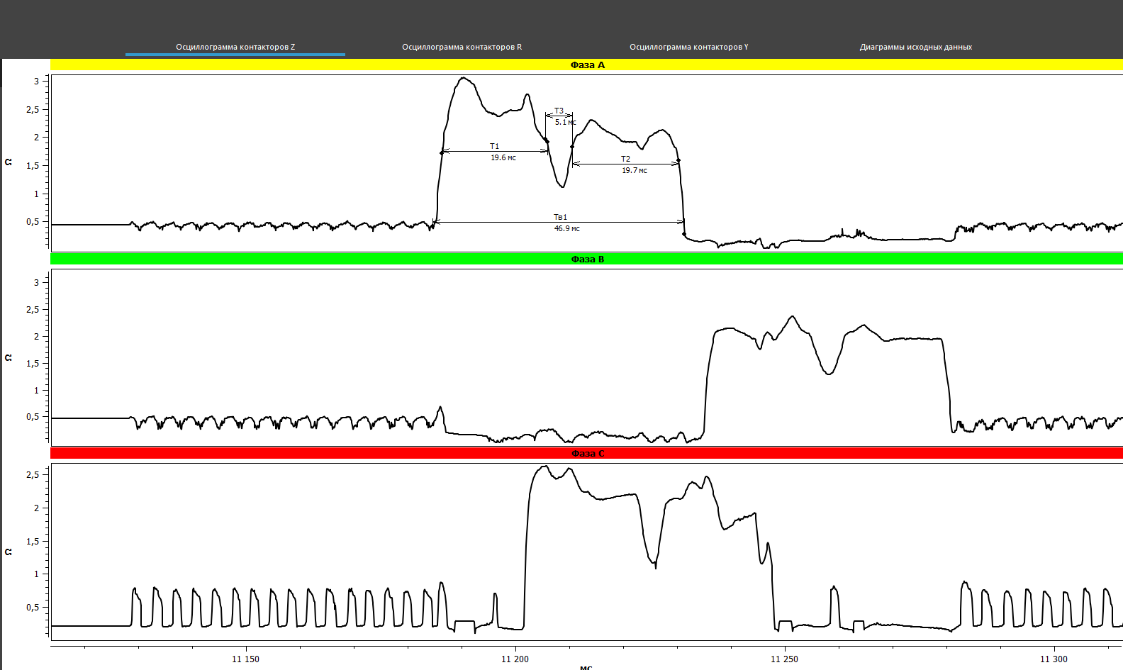
The results of oscillography made with the PKR group instruments are presented in the figures below (Fig. 10). In this case, on the oscillograms the bounce were noted in phases A and C, which were repeated at several taps, that may indicate a defect in the contactor contacts, and most often this is the contact burns.
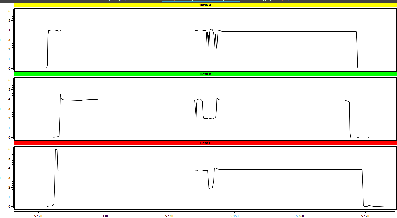
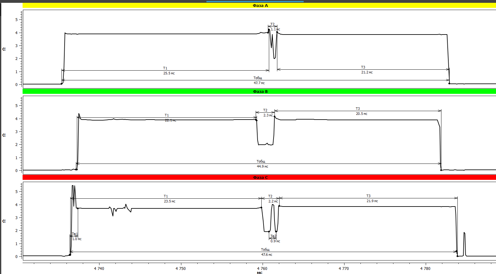
The oscillogram of the resistor OLTC with fixed malfunctions
After the received oscillograms and identified defects in the graphs - the contactor was removed from the tank and transformer. The preliminary assessment according to the graphs was confirmed (Fig. 11).
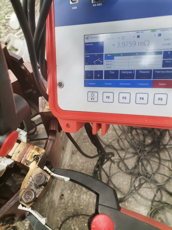
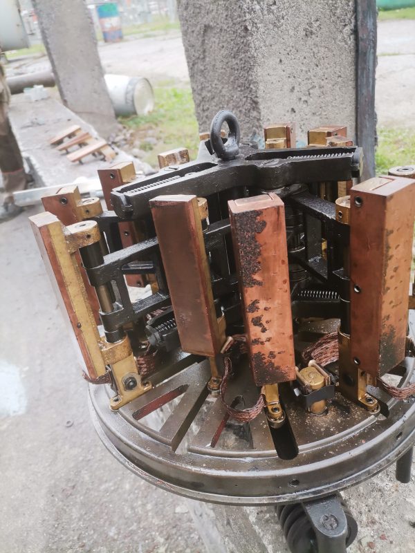
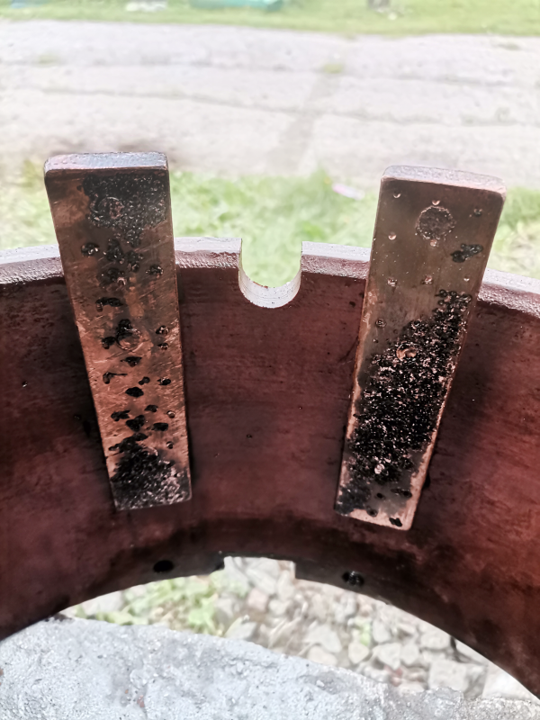
Figure 11. Contact burns
It is important to mention that circular diagram registration and oscillography for resistor devices made with an PKR group instrument is realized in one measurement, that significantly reduces the time for diagnostic.
DEMOUNTABLE DIAGNOSTIC OF RESISTOR OLTCs: CONTACT RESISTANCE OF CONTACTOR CONTACTS
The demountable diagnostic method allows you to check the contact resistance of contactor contacts, which can be carried out with micro-ohmmeters or milli-ohmmeters of SKB EP company from MIKO group. The measurement of the transient resistance of contacts and flexible connections is regulated for control (nominal data, or protocols before and after repair) and it must be observed both digitally with a help of special instruments and visually. As practice shows, the destruction of flexible connections can not always be determined by measurements, sometimes it is a visual inspection that is needed (Fig. 12).
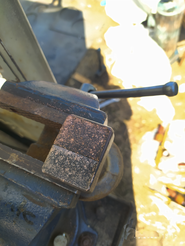
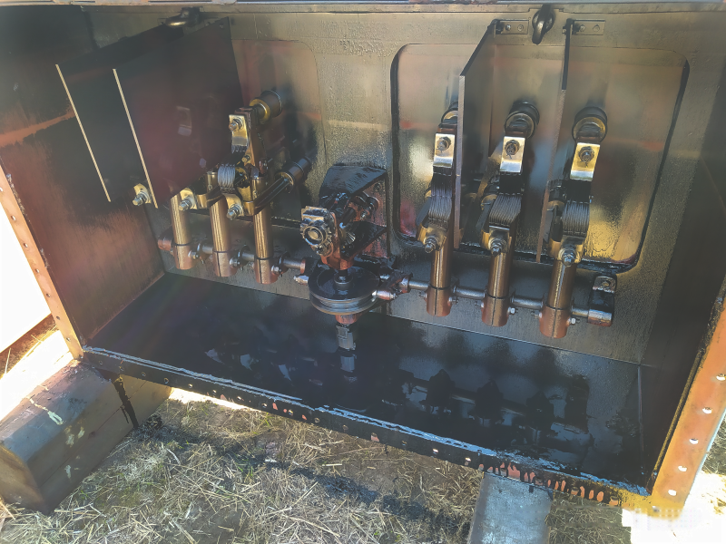
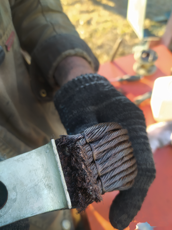
Figure 12. Contactor burns, flexible connection breakage
In conclusion, we underline that modern diagnostic equipment manufactured by SKB EP LLC from PKR and MIKO gives an opportunity to fully assess the operational performance of various OLTCs, define different incipient or already developing defects. Backlashes, rattling, tightening during actuation, the error in the operation synchronicity, breakages in resistances, incorrect operation of an OLTC, value overestimation of the contactor and selector resistances - all this and much more can be determined thanks to these instruments.
The use of devices of the PKR and MIKO group makes it possible to precisely determine the state of OLTC, precisely localize its defects, as well as correctly configure its operation and extend the service life of the device contact connections.
If you still have questions and you would like to get more information on some mode of operation of PKR-2 or PKR-2M instruments, please contact us by phone. +7 (812) 500-25-48, e-mail skb@skbep.com, the specialists of SKB EP LLC will promptly give answers to all questions.